A Journey from Resonance to Impedance Matching
Chp. 7: Quality Factor and Impedance Matching
One Must Not Tell Lies.
We have reached the finale of this saga. We have discussed how quality factor of a resonator led to signal gain and how did RF designers used that gain to boost impedance. Today we will look at how can we finally make a matching network out of this, and also a debunk a lie that has been and is continued being sold: “Bandwidth of matching network equals inverse of quality factor.”
Resonance to Impedance Matching
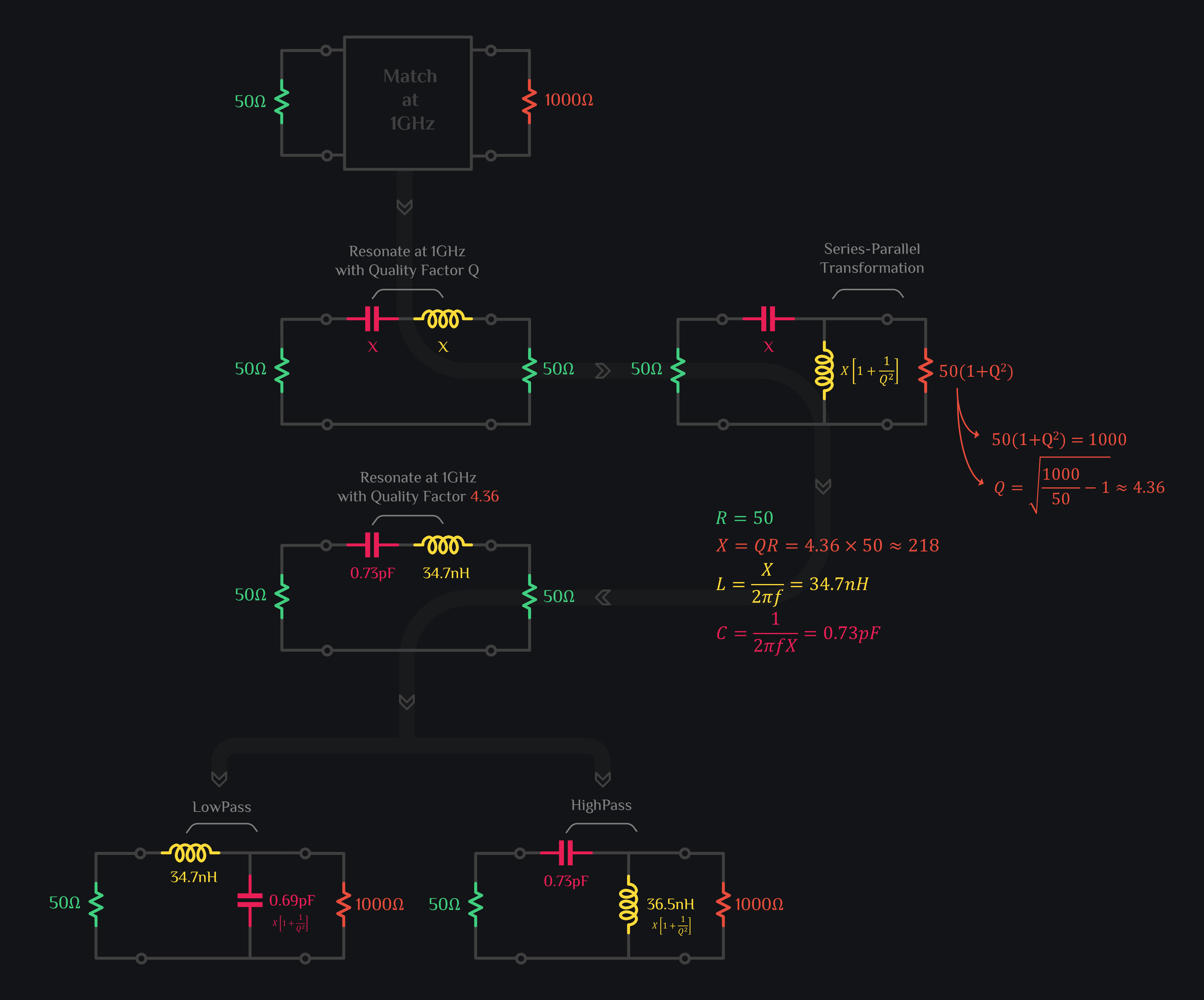
Say you want to match 50Ω to 1000Ω at 1GHz. Let’s take two 50Ω resistors and insert a 1GHz LC resonator between them. We know that voltage across reactance is Q times larger than resistance in a series resonator. We are going to exploit this and move a resistor across a reactance to tap this voltage gain. The moment you do that, the voltage gain drops heavily because that reactance just cannot drive this small resistor (after all its not an active amplifier). What we need to do now is to boost the resistor value by 1+Q2 to keep tapping that voltage gain. Now you have the opportunity to choose Q. Choose it in a way that the resistor becomes 1000Ω, and that Q comes out to be 4.36 as explained in image below. So you know now that you want your LC to resonate at 1GHz with Q of 4.36. From this information, you can figure out L and C values. So, that’s that. You have a series RLC resonator which will match the impedance if you place the resistor across reactance. And once you place it, of course you raise the resistor value from 50Ω to 1000Ω to keep Q intact. Which reactance do you place it across? Capacitive or Inductive? You can choose any. If you place it across capacitor, it will be a lowpass matching network. If you place it across inductor, it will be a highpass matching network. The latter is mostly preferred choice since you can use capacitor to DC block output and inductor to provide voltage bias to chip. And this is how L-matching networks were discovered by exploiting properties of a resonator.
Bandwidth of Impedance Matching Network
One of the common misconception that is found among RFIC designers (or should we dare to say a lie that is sold to them) is that bandwidth of a matching network is equal to inverse of Q. Right? You have seen this:
where FBW is fractional bandwidth \(\dfrac{\Delta \omega}{\omega_o}\) and \(\Delta \omega\) represents 3dB bandwidth around your center frequency \(\omega_o\).
(Its \(\frac{2}{Q}\) not \(\frac{1}{Q}\) because quality factor of series RLC resonator is halved – think about it, there are two 50Ω resistors – we worked out Q of 4.36 with respect to 50Ω but total series resistance is 100Ω, hence Q is halved. This is good for you because you get twice the BW)
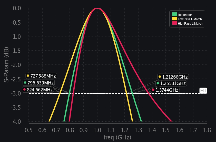
So even though Q does not predict exact bandwidth for matching network, it does serve as a pretty good indicator of bandwidth. You can for sure infer that if Q is high, bandwidth is going to be low. So the question then is what is the bandwidth of matching network, and does it ever equal to resonator bandwidth? Unfortunately, the exact bandwidth of matching network needs to be calculated by circuit analysis. We have not found a “magic formula” for it. The good news though is that bandwidth is almost to resonator bandwidth when Q is high. This makes sense because the series-parallel transformation that we did holds across frequencies when Q is high to begin with. For example if Q is 20, then even if it varies across frequency, say from 19 to 21 across frequency, that is relatively a small change. But if you began with a small Q, say Q of 3, and now if it varies across frequencies from say 2 to 4, that is a huge change. Your series-parallel transformation with these Qs will result in very different values of boosted R (we mean R(1+Q2)). And since you have a fixed R attached across reactance (1000Ω in our case), your impedance transformation will be ruined, and behavior of L-match will start differing from behavior of resonator across frequency – hence different bandwidths.
Next question: how different is L-match bandwidth from resonator bandwidth. Let’s say you would settle for 5% inaccuracy in bandwidth, that is if \(\frac{1}{Q}\) gives a bandwidth which is within 5% of actual bandwidth, you would say “meh, ok, I take it, I don’t want to calculate exact bandwidth anyway, it does not matter much for me, all I care about is that I could easily design matching network with Q-factors and I have a rough idea that \(\frac{1}{Q}\) bandwidth is going to be close enough to my actual bandwidth”. In that case, we recommend to ensure Q of your L-match is greater than 5 for low pass L-match, and greater than 8 for high pass L-match, then you are guaranteed to have less than 5% bandwidth difference as shown in image below.
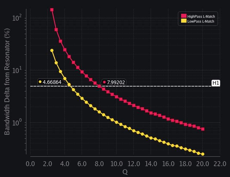
Image above also shows how quickly bandwidth delta grows for lower Q. For example, if Q of your L-match is less than 3, you can clearly see bandwidth delta is greater than 100% (for highpass L-match), that is your actual bandwidth is going to be much higher than what is predicted by Q of your circuit.
Alright folks – this concludes our journey from resonance to impedance matching. Hope you had fun taking this journey and it was insightful.
Good Reads (External Links)
Browse by Tags
RFInsights
Published: 11 March 2023
Last Edit: 11 March 2023