Chp. 5: Quality Factor and LC Tank Behavior in Time Domain
To develop further intuition in Q-factor and extend its application to matching and bandwidth, it is prudent to study time domain behavior of LC tank. We show how an LC tank starts up, how the voltage developed across it heads to infinity, how a finite Q-factor limits its growth, and what happens if you excite the tank with non-resonant frequencies.
Transient Response of LC Tank
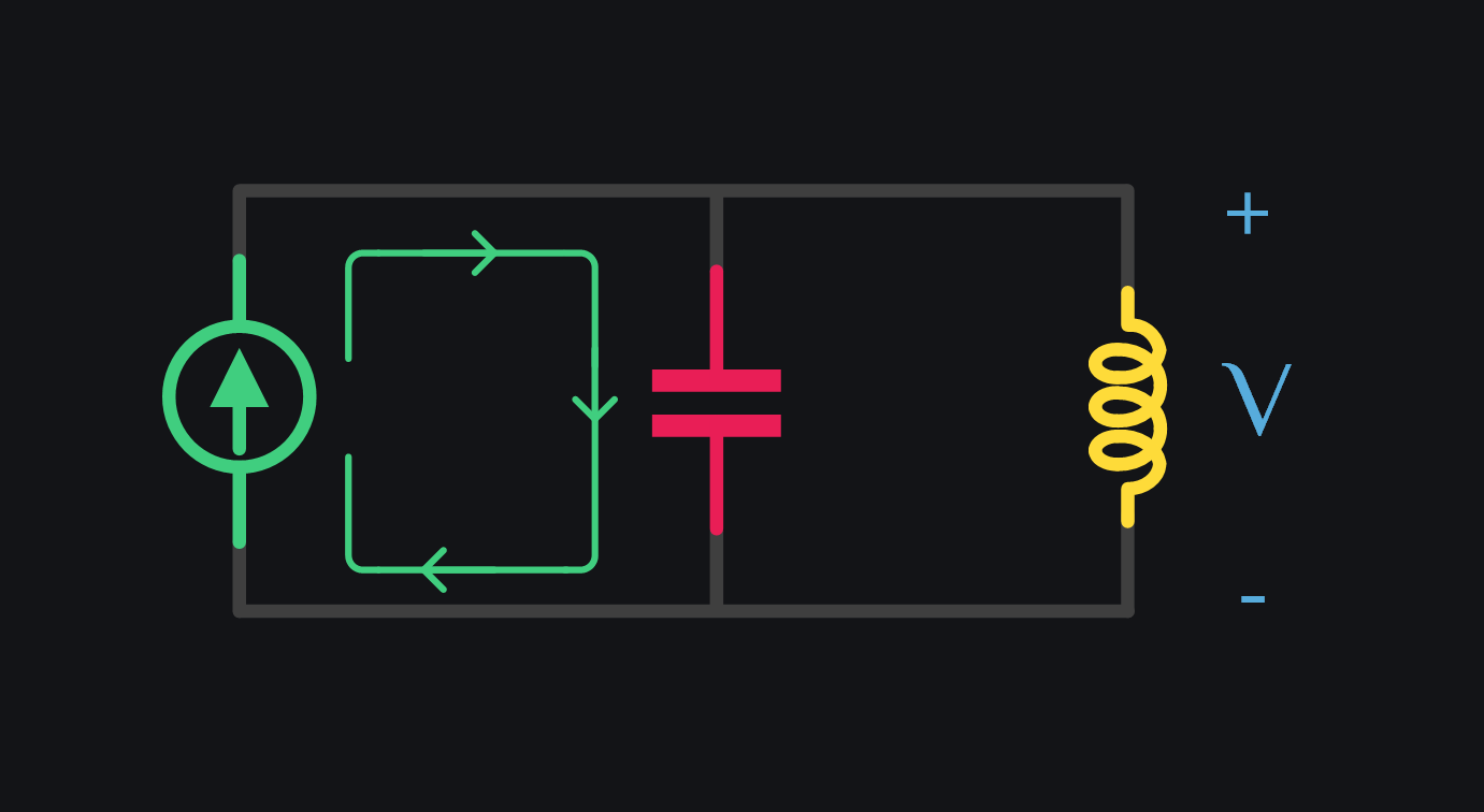
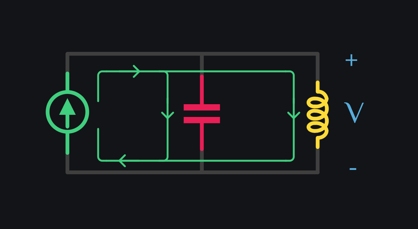
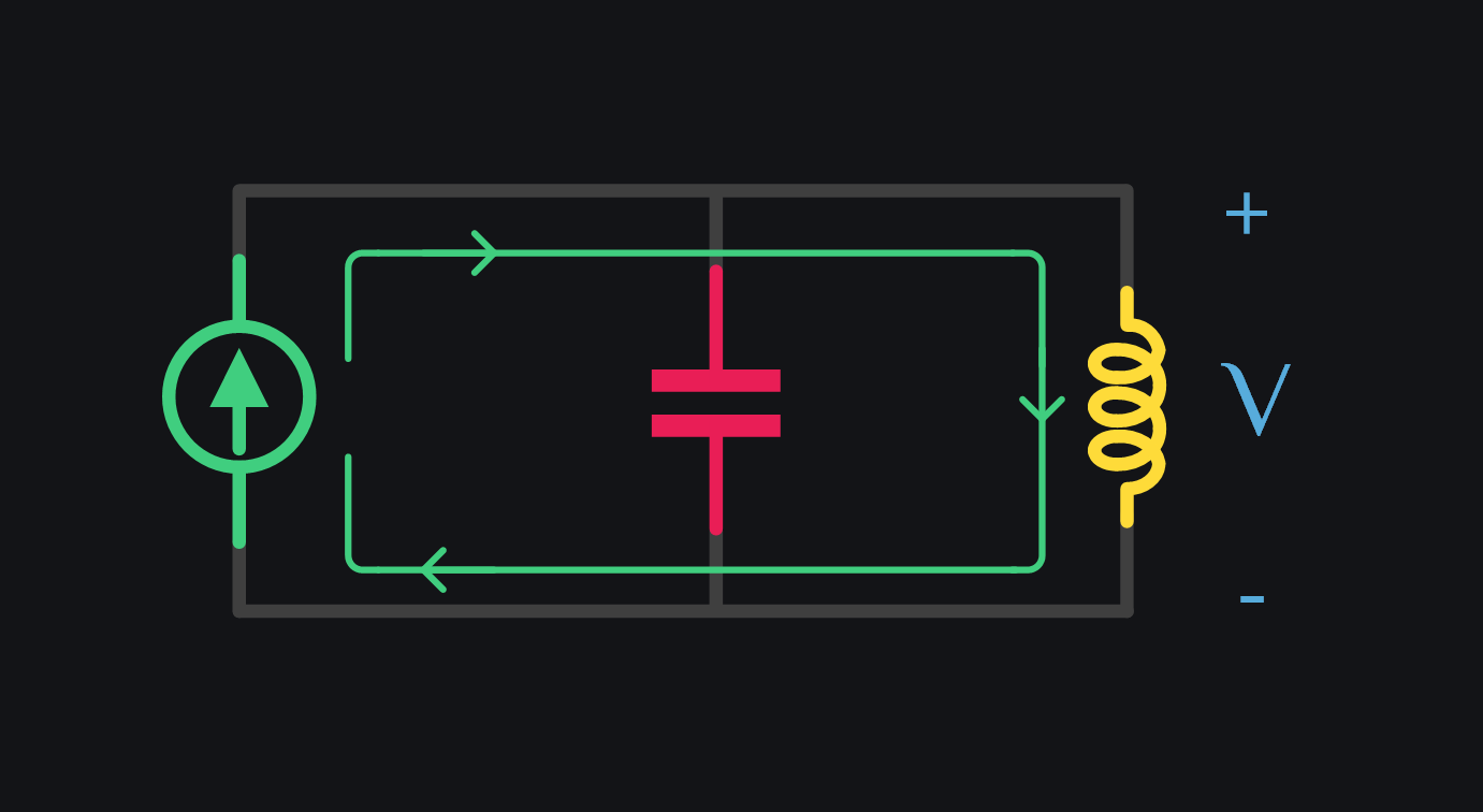
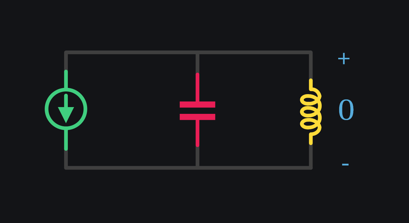
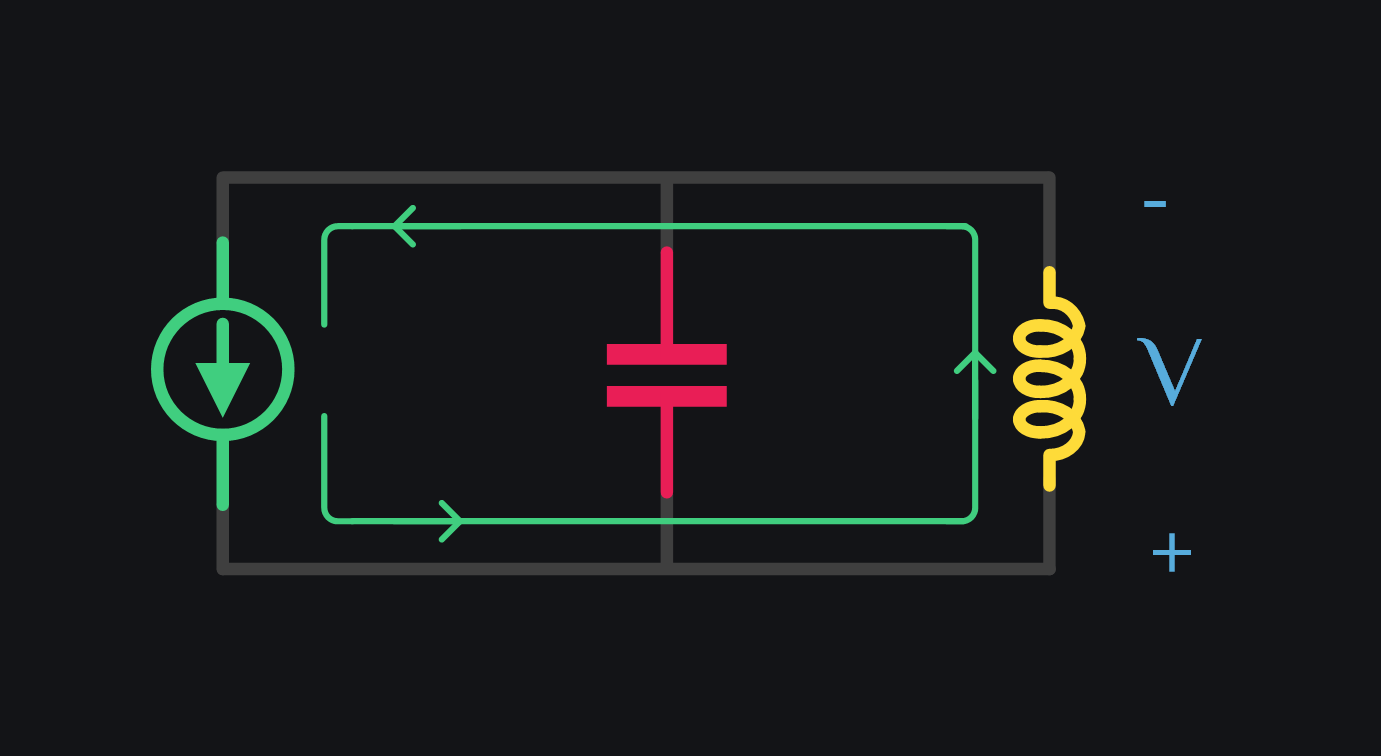
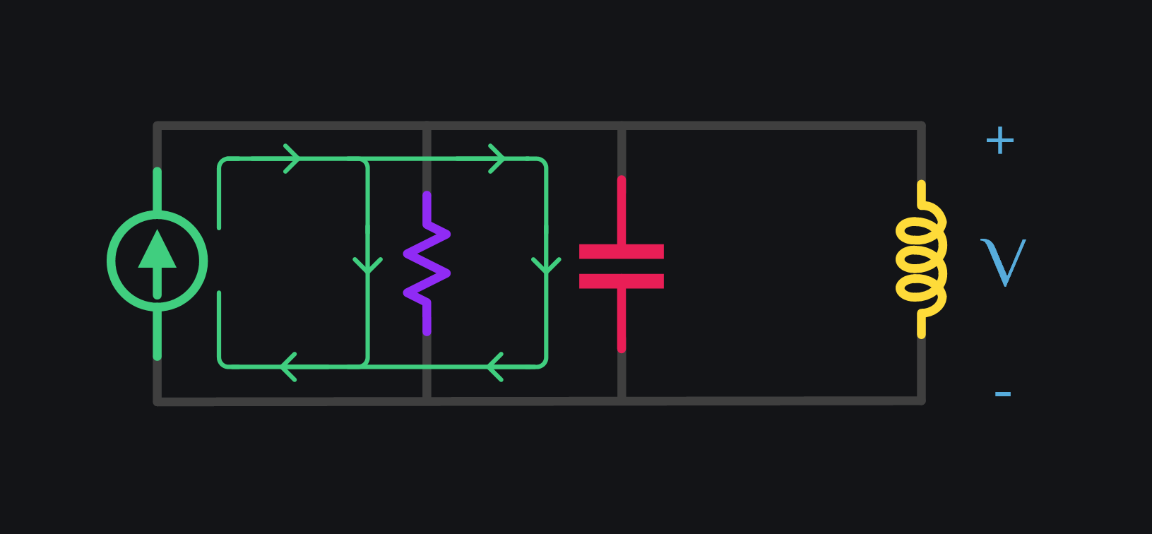
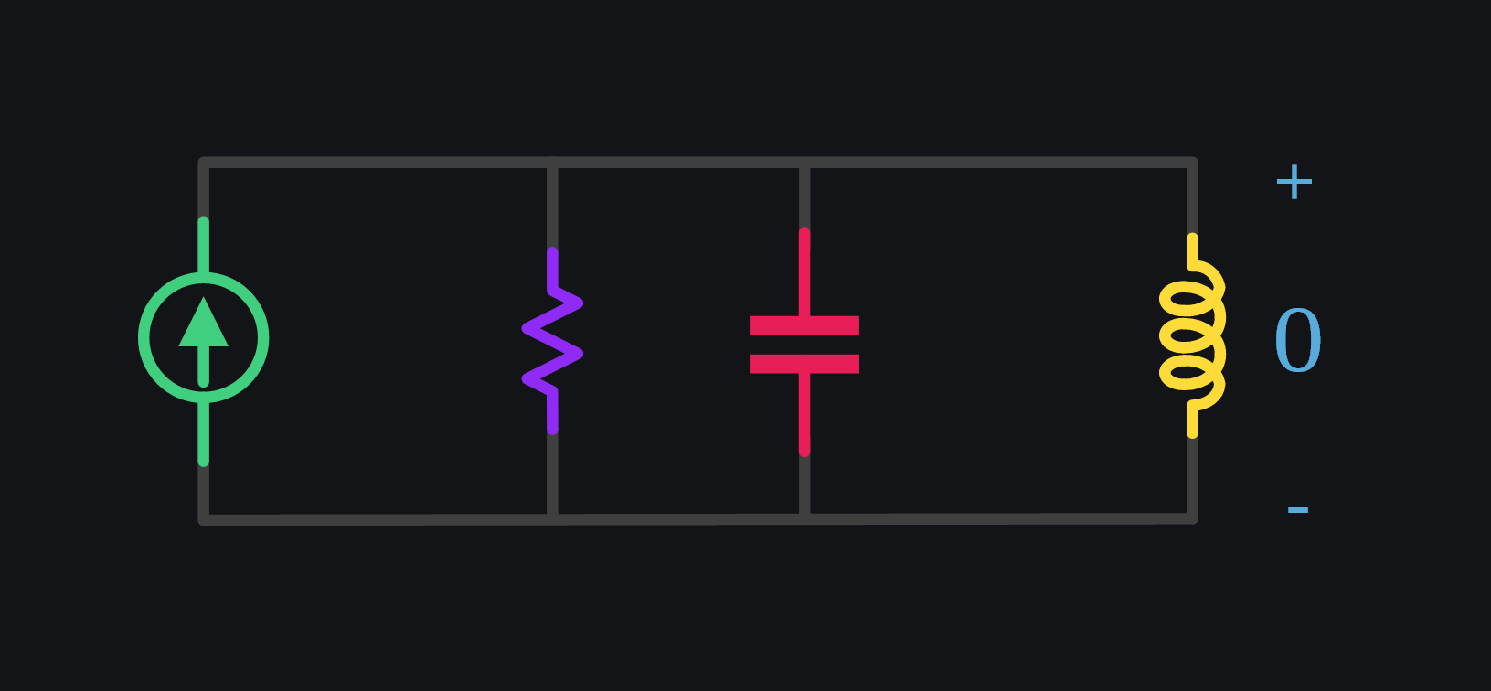
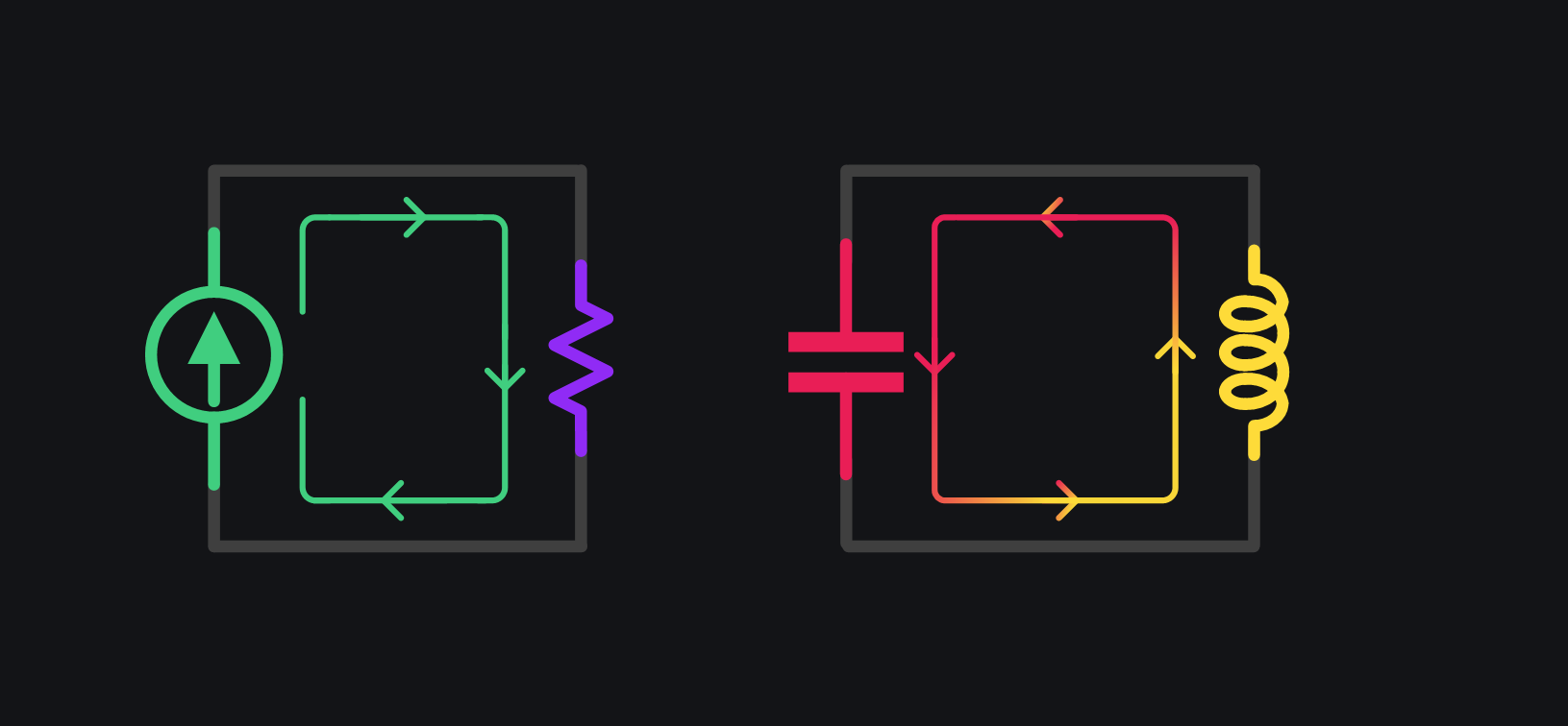
Attach a sinusoidal current source of 1mA with 1GHz frequency to an LC tank which is also set to resonate at 1GHz. Let’s see how things play out.
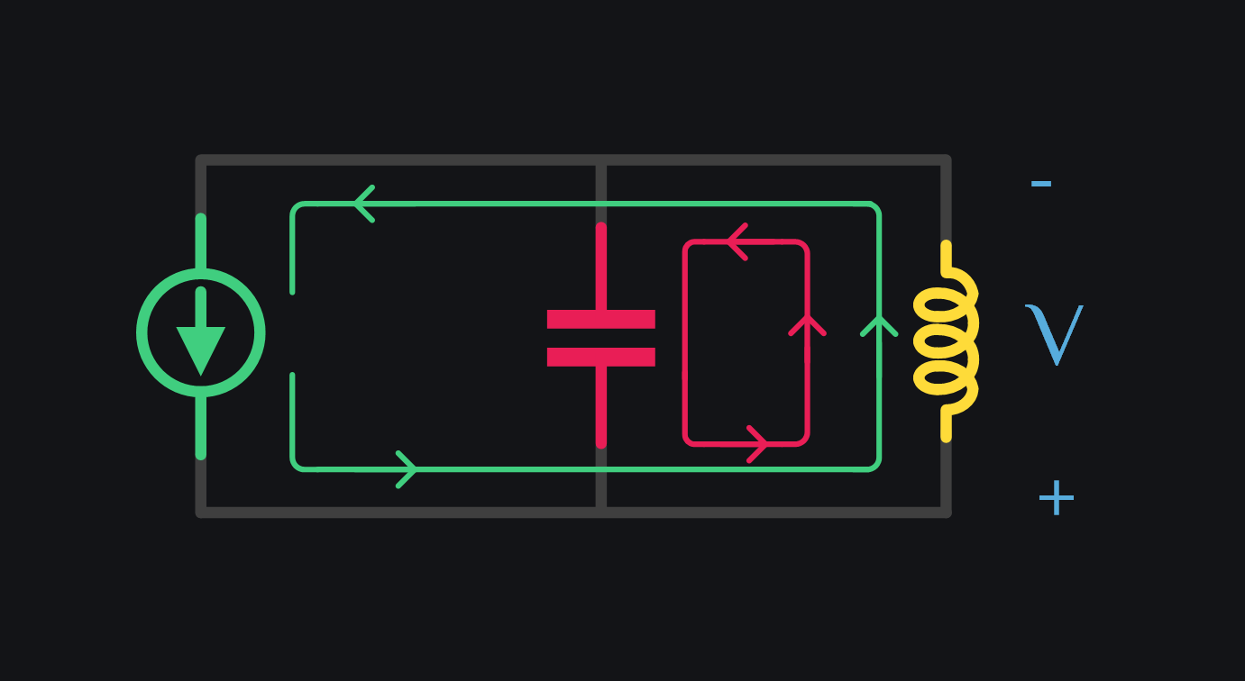
V1: Current through inductor cannot change instantly. It begins slow letting cap take all the source current.
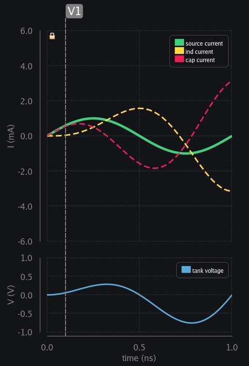
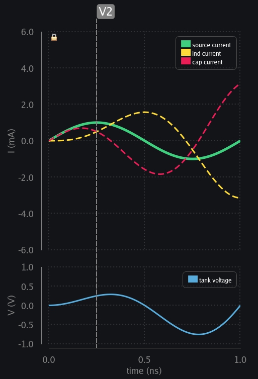
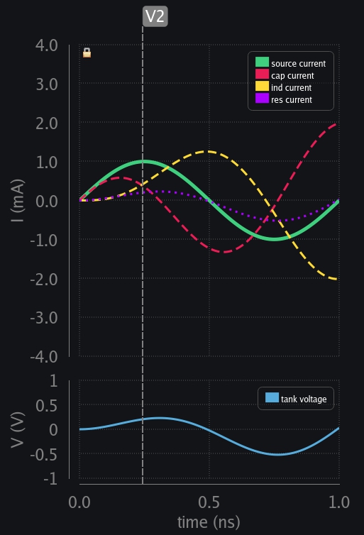
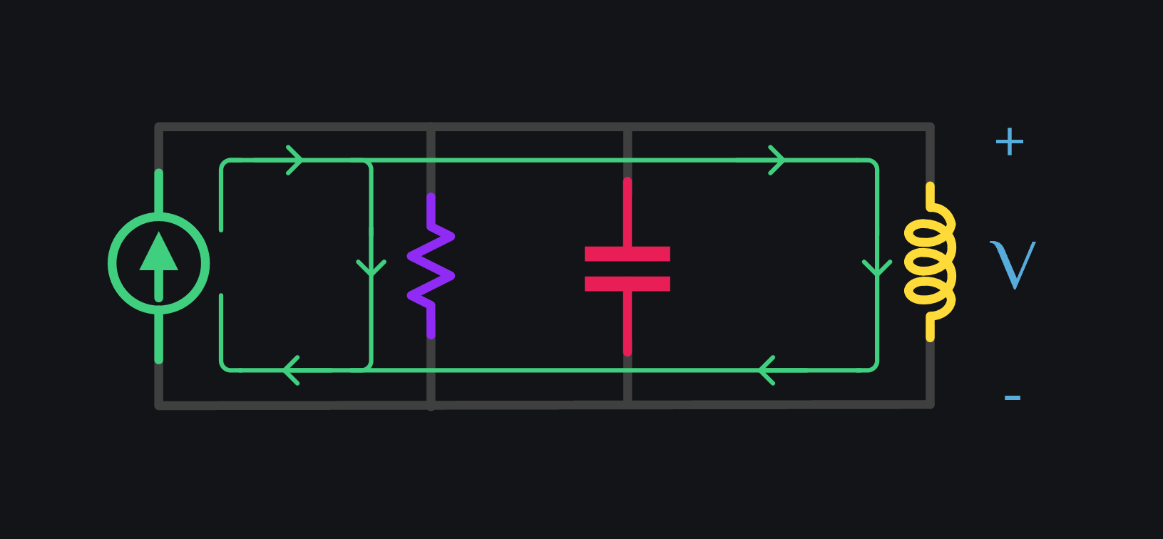
V2: There is only limited current available from source. As inductor starts taking more and more current, cap current decreases.
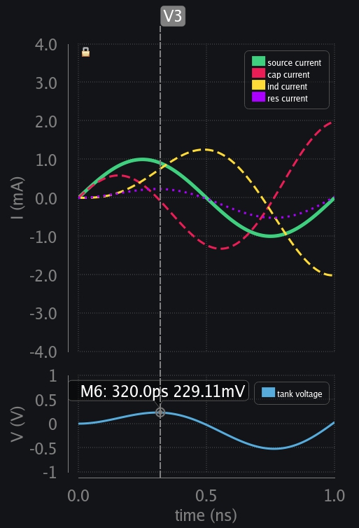
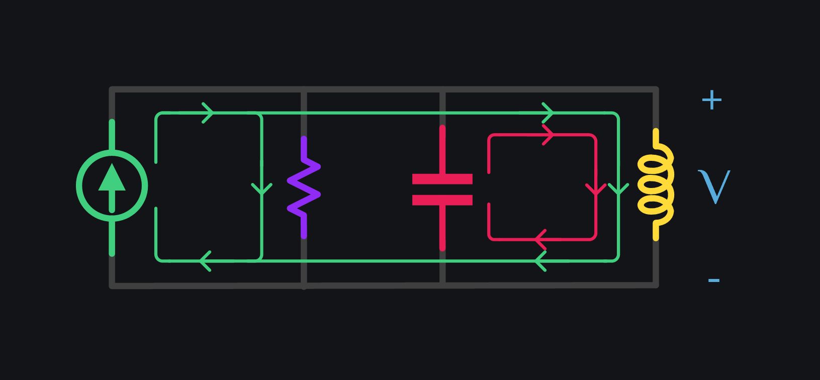
V3: Inductor has taken all the current. Cap current goes to zero and cap reaches max voltage because it did not discharge so far. It had been charging and charging. Now we can appreciate why we say current leads the voltage in capacitor by 90 deg.
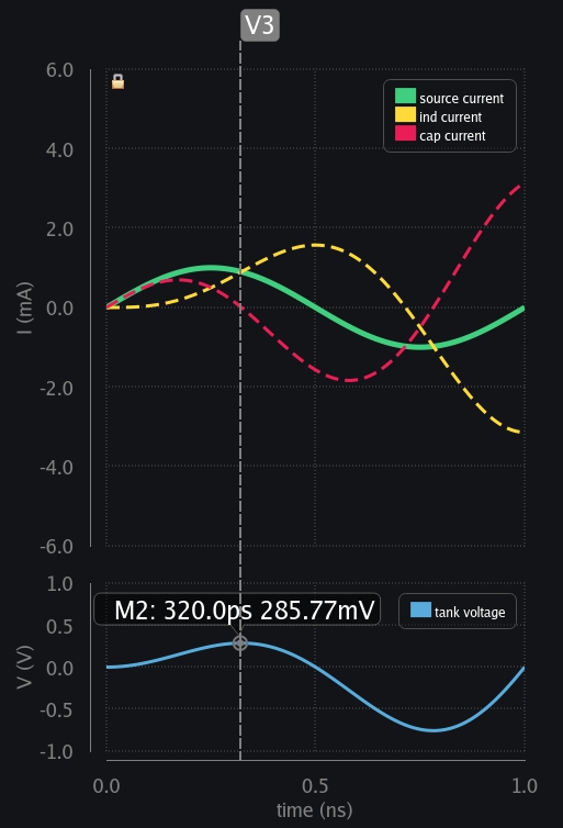
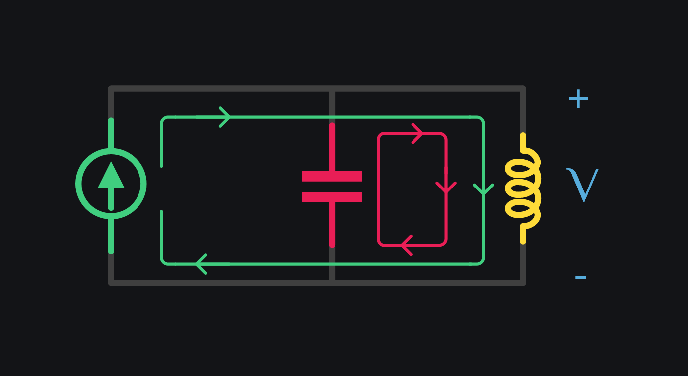
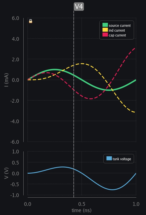
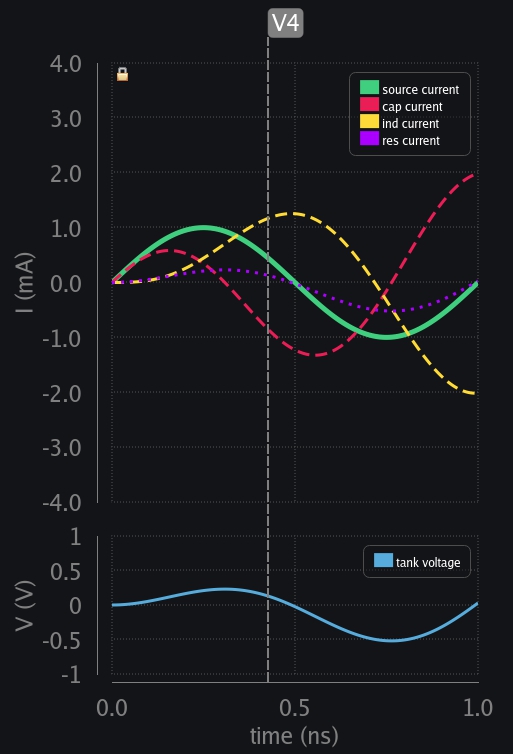
V4: Inductor had taken all the source current but now source current is falling, that is a sudden change for inductor which cannot happen. It needs to keep going, so cap kicks in. It discharges by providing inductor extra current it needed. Watch the inductor current – it has risen above source level. Can we call it current gain? Yes if we can control it, and we will.
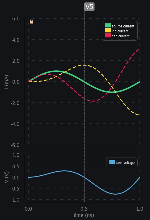
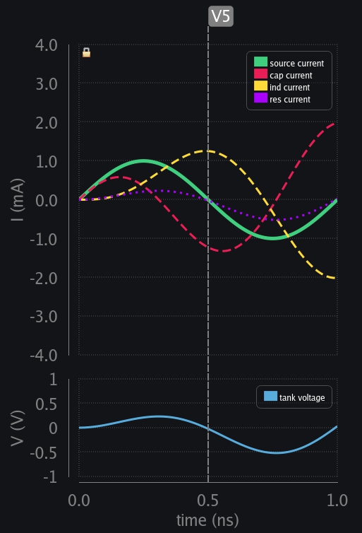
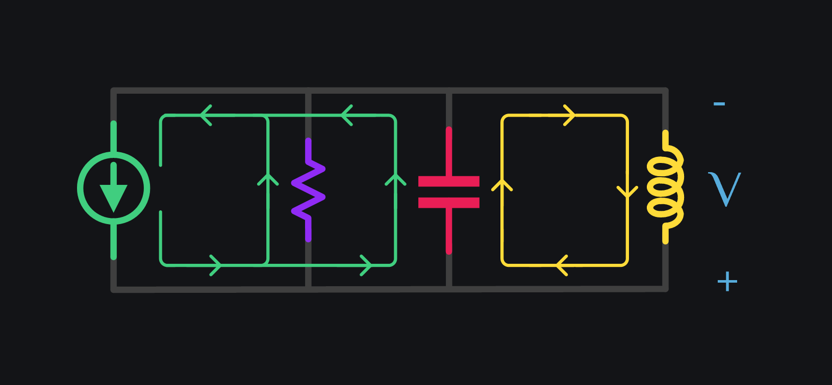
V5: Cap charge exhausted. Cap voltage is zero, and source current is zero too. See how did source and cap zero crossing aligned. This will prove to be important later on.
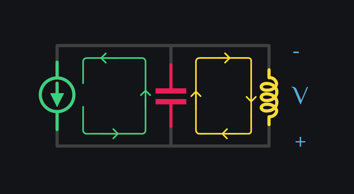
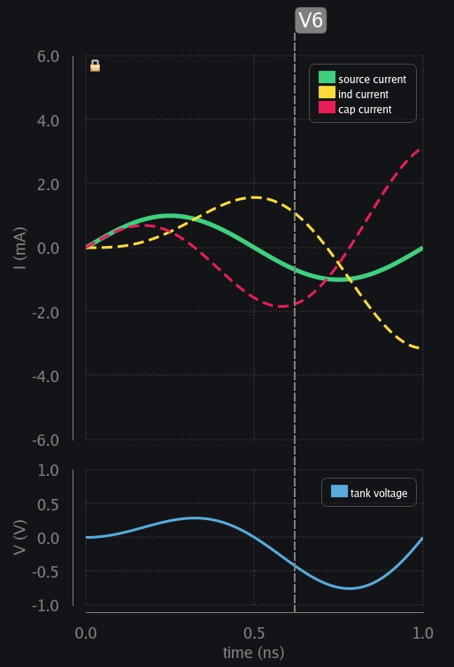
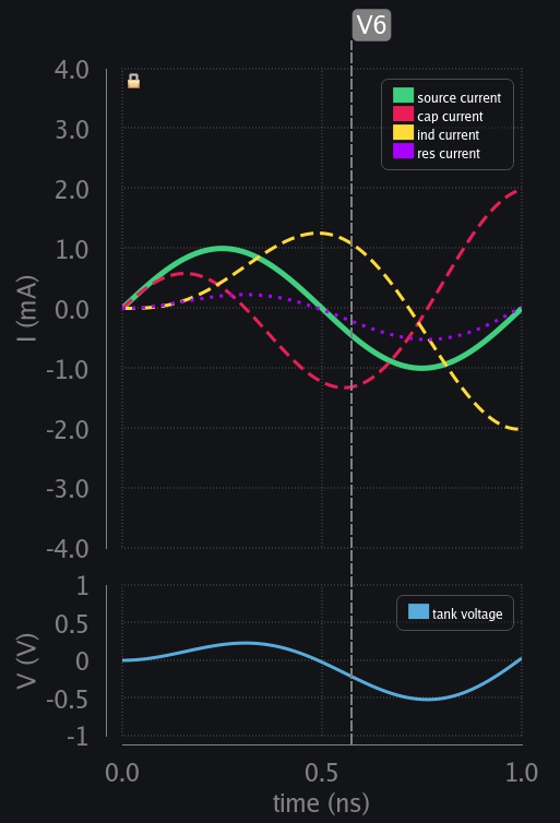
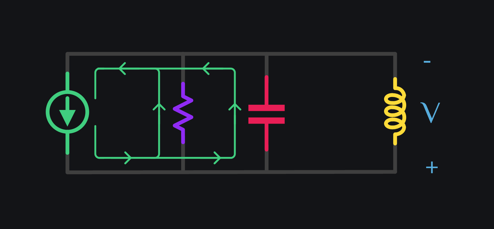
V6: Source reverses the direction, and starts charging the cap in opposite direction. Inductor still has positive current going and it just cannot change its direction like that. So, it flips the voltage around it to maintain the current direction and starts providing charge to cap. Watch the current – it has risen to a higher level than before.
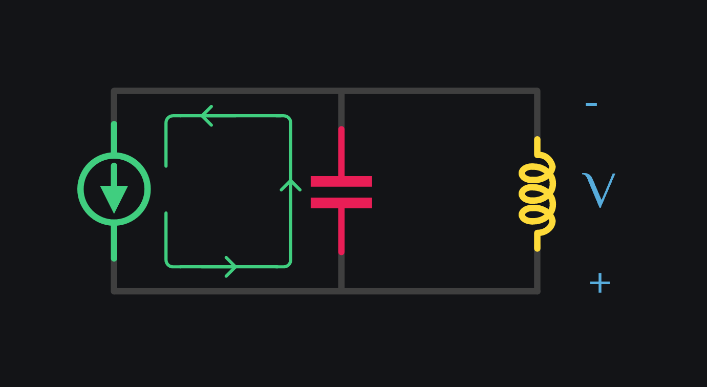
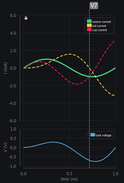
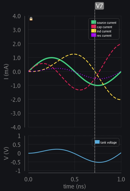
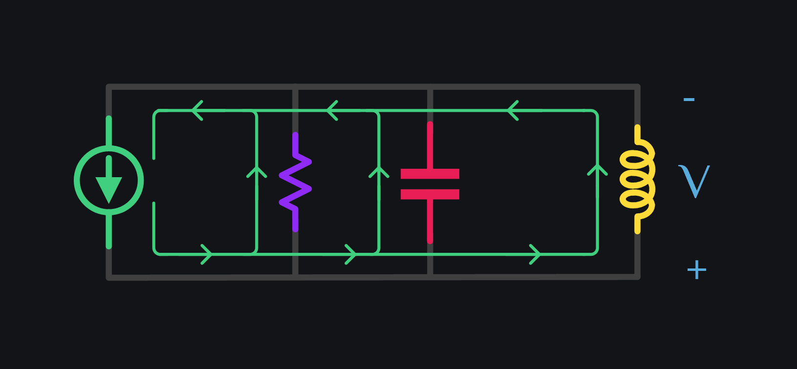
V7: Inductor has exhausted all the energy it stored. Cap keeps taking current from source.
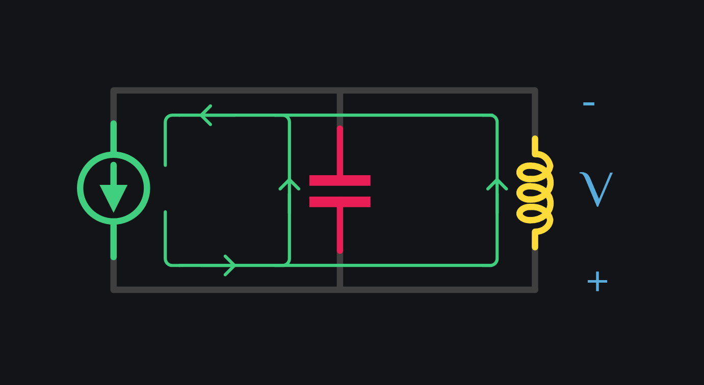
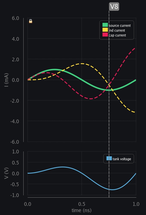
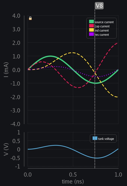
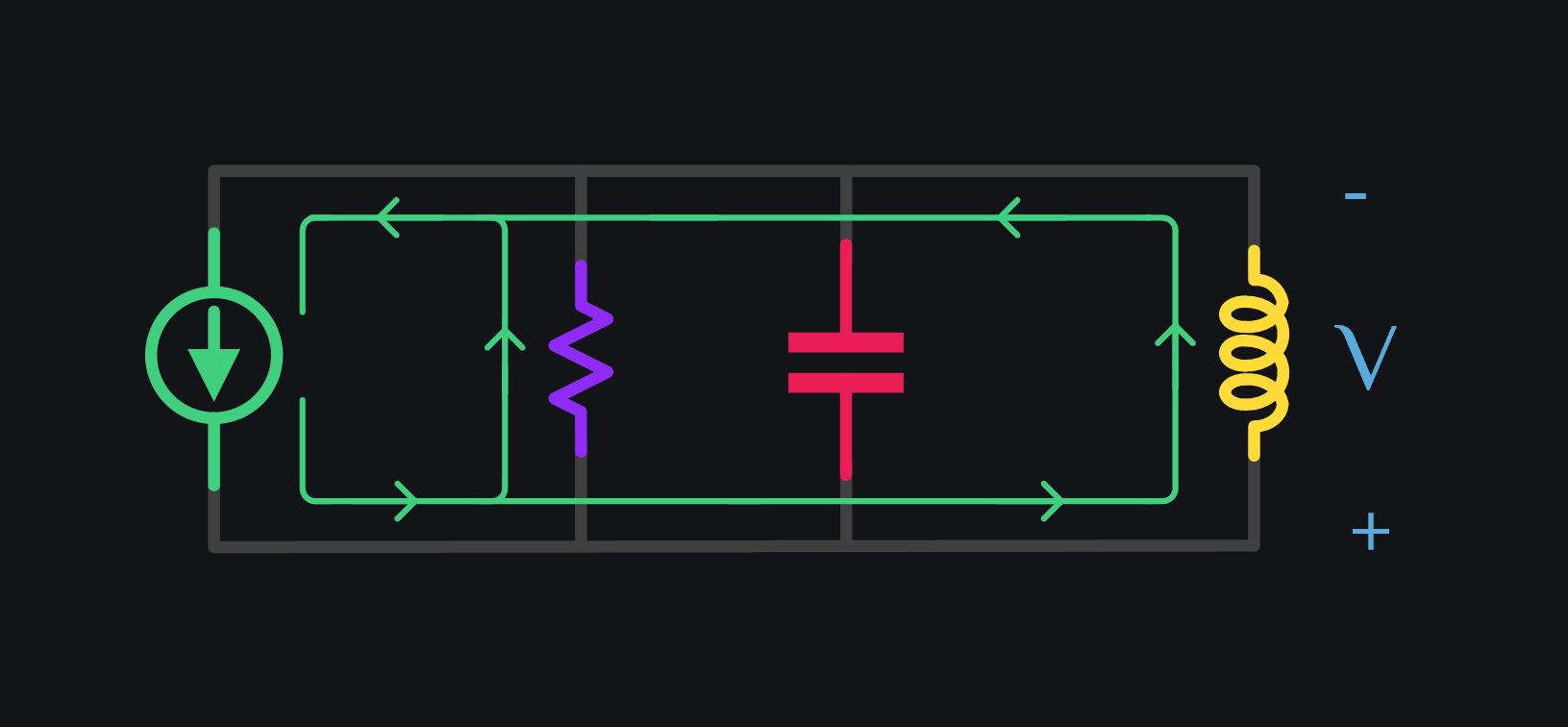
V8: Inductor also begins to take the current in reverse direction now. Cap and ind both share source current.
V9: Soon ind again takes all the current from source leaving nothing for cap. No more charge current available to cap? so then it has reached its max voltage (in negative direction now)
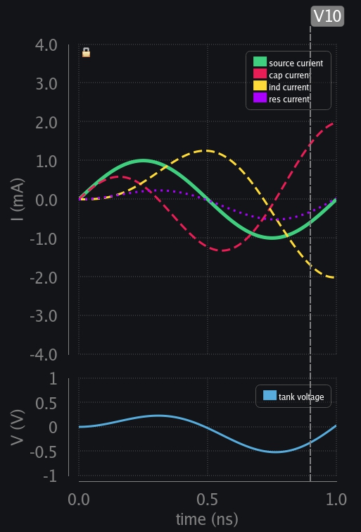
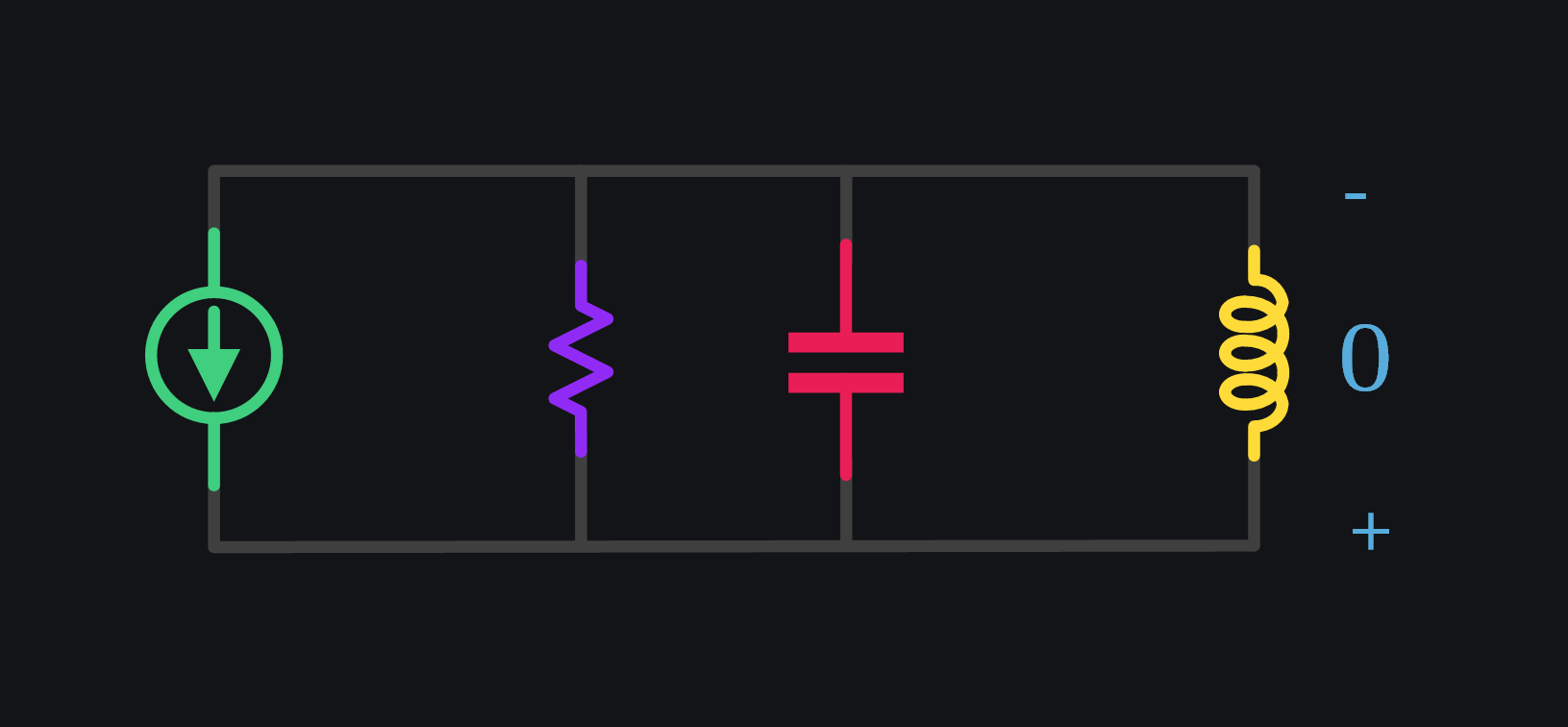
V10: Source current is again reducing but ind has to keep going because again ind does not allow sudden current change. So cap kicks in again and start providing for ind. You see the cycle here? How the other guy kicks in when source is not able to provide. This keeps going and in each cycle current rises to a new level than before. They keep exchanging charge between themselves plus keep taking more charge from source. Result? This is heading to infinity.
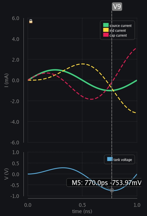
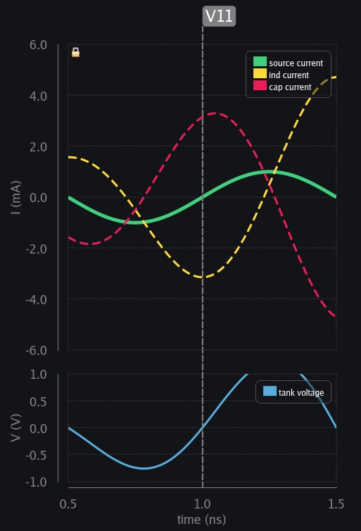
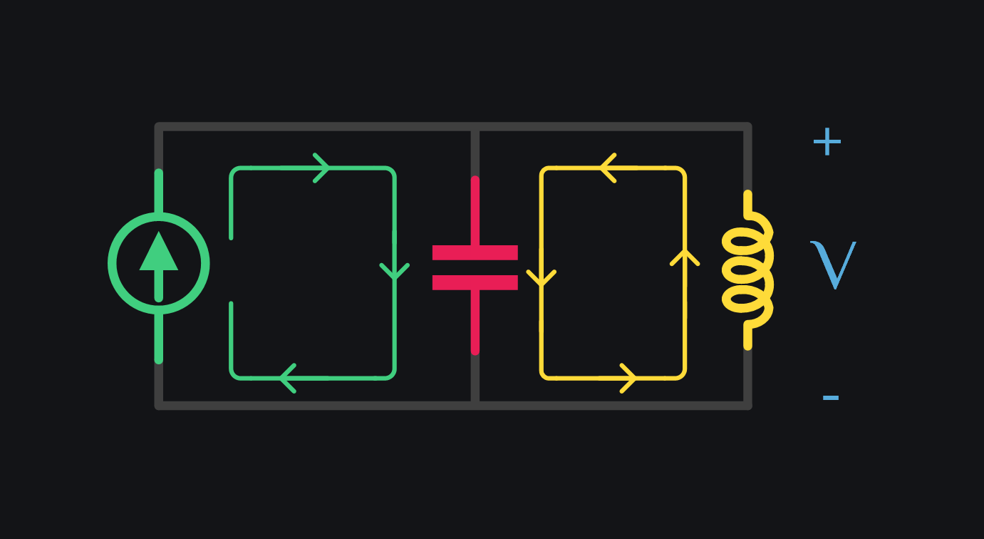
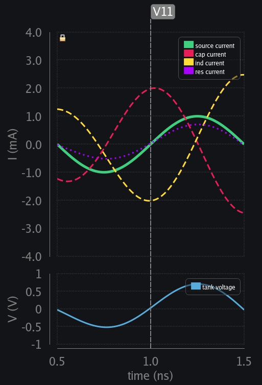
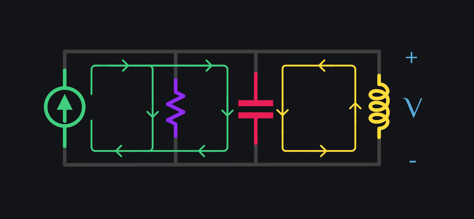
V11: Source reaches zero crossing and so does cap voltage. Cap has got no charge now, its all the ind current which is flowing between them, therefore the direction is opposite i.e., ind sourcing and cap sinking. Now we can appreciate why we say ind and cap current is always out of phase in parallel LC tank.
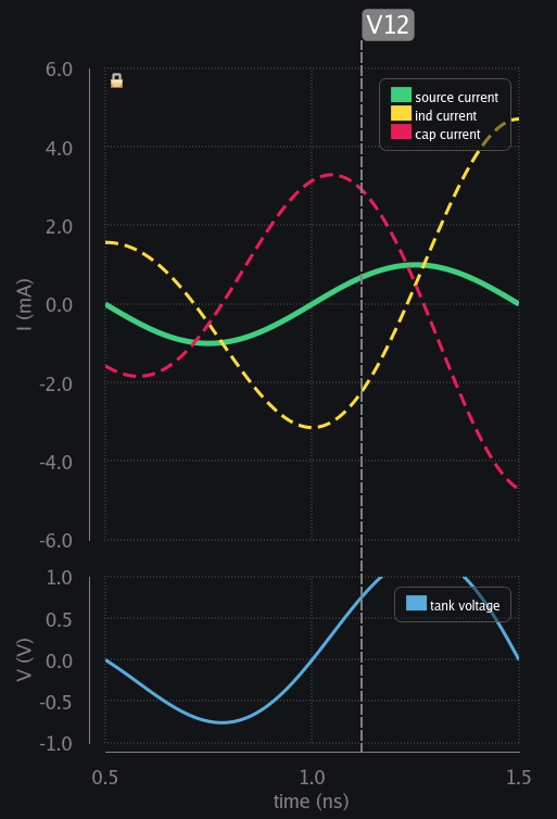
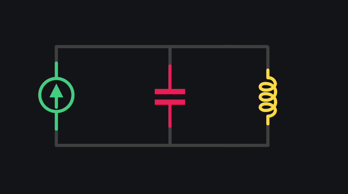
V12: Source wants to charge cap in positive polarity now. Ind says no. I cannot take positive current at the moment. Let me first get rid of my build-up current (or magnetic field whatever you want to call it). Voltage is flipped again and ind starts charging the cap.
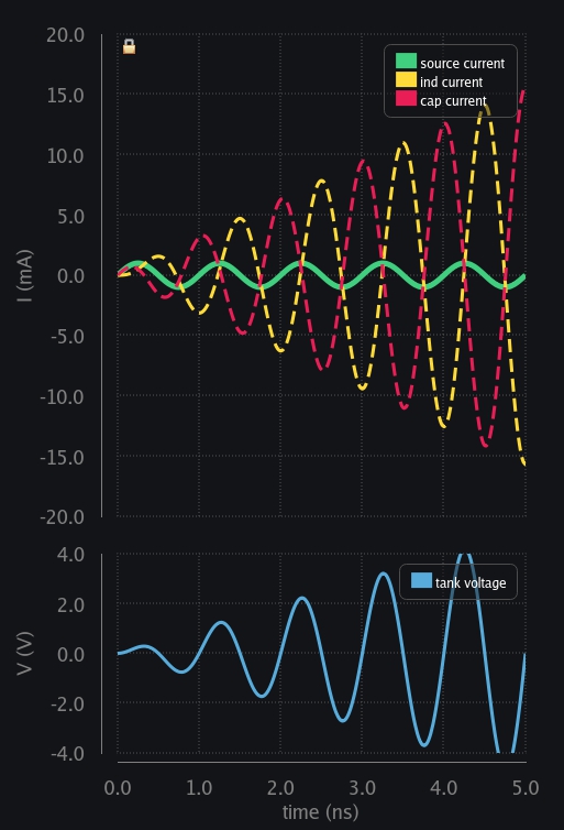
So eventually things blow up to infinity. Cap and ind keep exchanging charge between them plus keep taking more charge from source. Nobody is losing nothing. Current in the tank keeps rising, and so does voltage across it.
Transient Response of LC Tank with finite Quality Factor
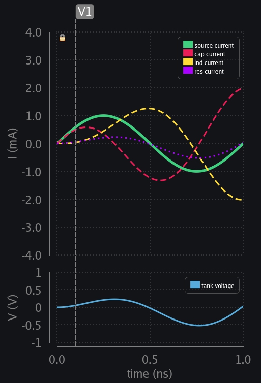
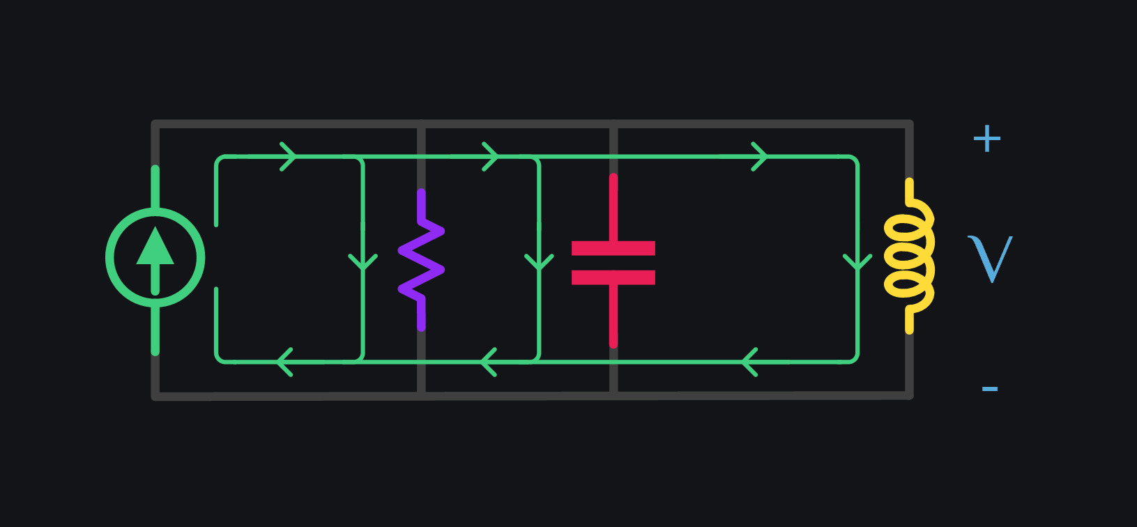
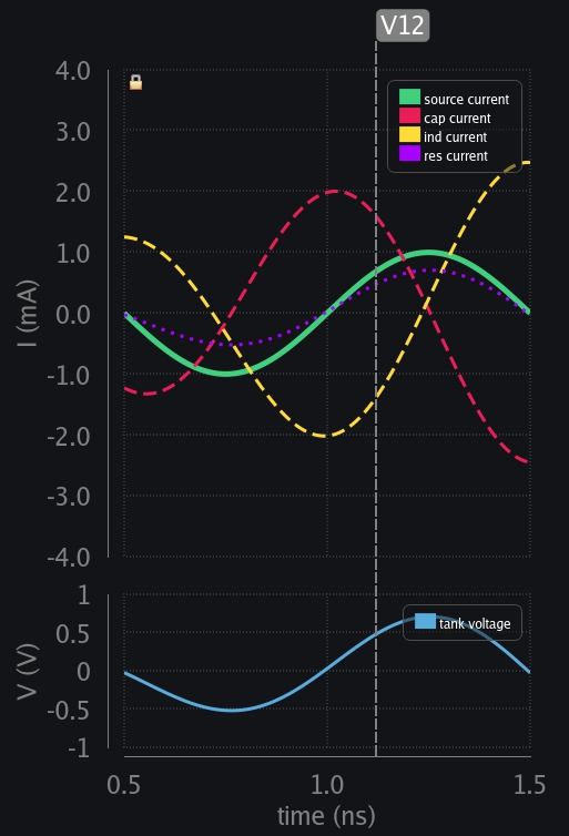
We are going to do same experiment as above but now with an LC tank with finite quality factor. Let’s attach a resistor of 1kΩ to an LC tank set to resonate at 1GHz, and excite this tank with 1mA current source with 1GHz frequency.
V1: Current through inductor cannot change instantly. It begins slow letting cap take all the source current. Voltage developed across tank is also very small at this point, so resistor also does not draw in much current.
V2: Ind current keeps taking more current from source and so does resistor.
V3: Time comes when ind and res has taken all the current from the source. Cap current falls to zero, and cap has reached max voltage. But note that this time the voltage is lesser compared to the case with no resistor (229mV vs 285mV). This is an early indication that source just does not deliver all its charge to tank now, some part of it gets lost in resistor.
V4: Ind needs to keep going but source is decreasing. Resistor can follow source but for inductor that is a sudden change. Cap kicks in and starts delivering its charge to inductor.
V5: Source exhausted and so did cap voltage. Inductor current reaches its maxima because there is no one left now to provide any charge. See how resistor was able to follow tank voltage but inductor has its current at peak instead when voltage collapsed. Now we can appreciate why we current in inductor lags the voltage by 90 deg.
V6: Source wants to charge cap in opposite direction now. Ind cannot flip the current suddenly, so it flips the voltage, and starts discharging through cap. Resistor is kind. It follows whatever LC are trying to do. Whatever voltage they develop, resistor only draws that much current.
V7: Ind current has collapsed. Cap keeps taking current from source but watch now res is drawing more and more current from source as time progresses, leaving less and less for cap to build-up its charge.
V8: Inductor also begins to take the current in reverse direction now. Cap, ind and res – all share source current.
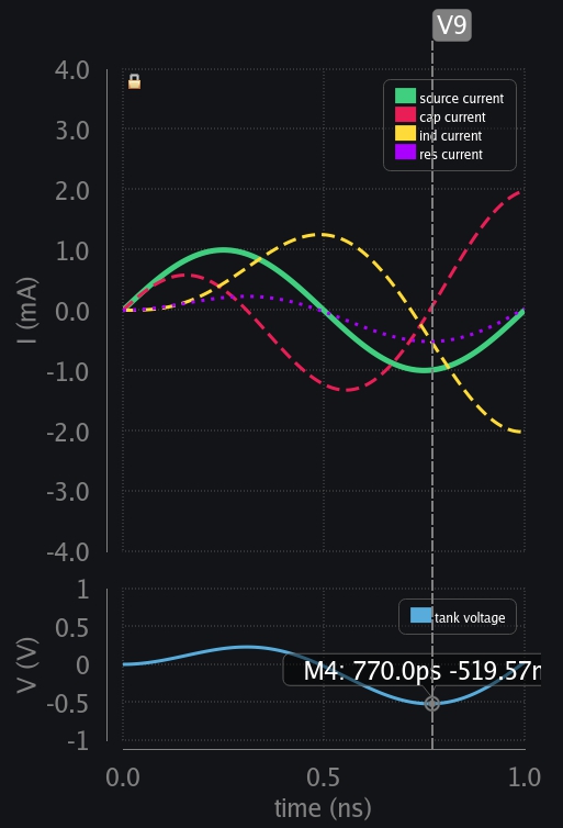
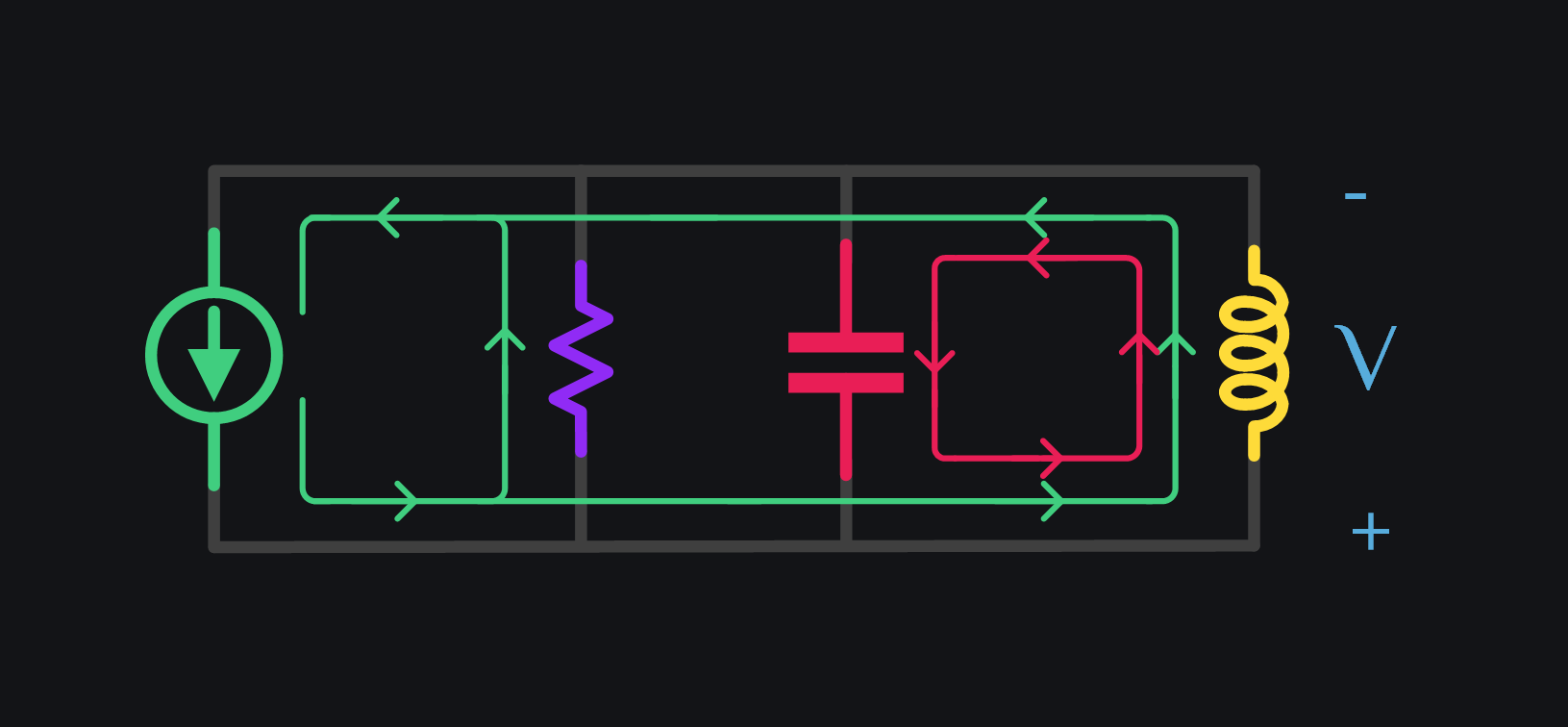
V9: Time comes when ind and res has taken all the current from the source. Cap current falls to zero, and cap has reached max voltage (in opposite polarity). But note that this time the voltage is lesser compared to the case with no resistor (519mV vs 753mV). An indication that voltage build-up is slowed down, and maybe will stop at some point? We will see.
V10: Source is falling but ind has to keep going. Cap kicks in, discharging through ind and giving it the extra current it needed. You can also observe that current has not risen to the levels it had risen when there was no resistor. You can also think of it this way: there is no resistor but current source has just reduced from 1mA to x mA, and this x is reducing with time. And after things are past transient period, this x will eventually go down to zero.
V11: Source reaches zero crossing and so does cap voltage. Look at res current waveform now – see how it is almost becoming equal to source current – leaving very little for ind and cap.
V12: Source wants to charge cap in positive polarity now. Ind says no. I cannot take positive current at the moment. Let me first get rid of my build-up current. Voltage is flipped again and ind starts charging the cap. Source also wants to charge cap but now resistor is starting to take almost all of its current (resistor’s demand is going up and up because voltage across tank has been growing up and up)
So things play out a couple of cycles. Charge exchanges between ind and cap, while taking in extra from source each cycle. At one point, tank has developed so much voltage (by storing and taking in more from source) that resistor would start drawing ALL of the source current. For our case, this is 1V because we had 1k resistor which can develop 1V with 1mA current. The voltage cannot grow anymore because resistor would need to dissipate current which is higher than source current and that is not possible. So all this drama stops at this point. Things have settled. Ind and cap had stored whatever they could, and now they can keep it, exchange between themselves while the source can keep driving the resistor. It is as if like LC tank has gotten disconnected from source. It does not take a bit from source, and does not lose a bit too. It keeps on going at whatever current it could develop which is about 3mA for our case. Now million dollar question: why 3mA? What determines this number? Ans: Q-factor.
Comparison of Transient Response of LC Tank with different Q-Factors
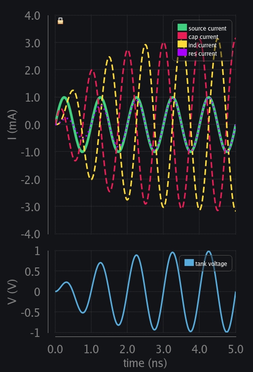
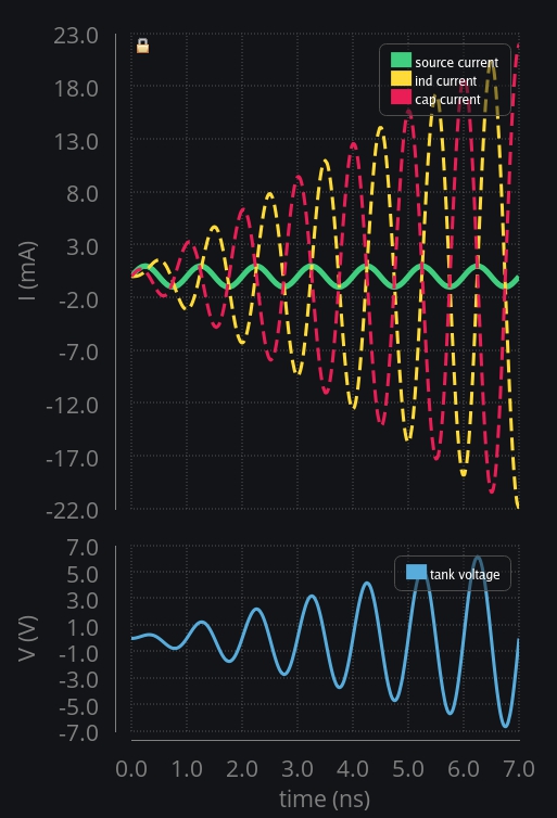
To drive our point home, let’s compare RLC response with different Q-factors.
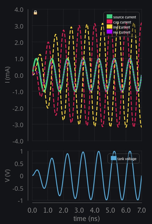
Left image: L=50n, C~0.5p to resonate at 1GHz, no R, thus Q=inf. Each cycle ind and cap exchange charge between them plus current source adds in too. Total charge/current/voltage/energy whatever you like, keeps on adding up. This is headed to infinity.
Middle image: Same LC but with R=1kΩ, thus Q=3.2. Each cycle ind and cap exchange charge between them plus current source adds in too. But with time resistor draws more and more current from source until it has taken all the current and leaves nothing for LC tank. Charge in tank stops piling up. Whatever LC could store, that is going to be the voltage or current in the tank. We can clearly see current in LC tank is Q times higher than source or resistor current. You can call it amplification at this time (instead of oscillation), and make use of this current gain, just like we used voltage gain for impedance transformation.
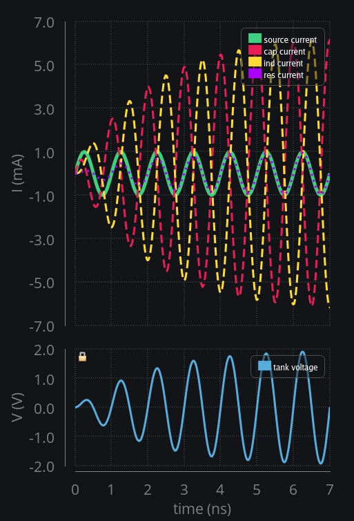
Right image: Same LC tank but with R=2kΩ now, which doubles the Q to 6.4. Now observe. Resistor is doubled, meaning for it to absorb all the current, voltage has to reach 2V, that means LC tank has more time or cycles in taking the charge from source current. That is why the current in tank could now build up to 6mA! So in essence, a higher quality factor is just giving tank more time to take in more from source, and thus results in bigger current gain. This aligns with our expectation that quality factor is nothing but number of cycles it takes for a resonator to lose (or build) the energy.
One more thing to observe: when there was no resistor, current in LC tank was rising in a linear fashion. However, with a resistor, it rises exponentially. This has to do with fact that RC charging and discharging is exponential in nature.
Transient Response of RLC with non-resonant Frequencies
If you force an LC tank at a frequency which is not natural to it (and that is everything except resonant frequency), it wouldn’t be able to develop the max voltage it could or in other words current source would never be able to deliver the power it could in resonant case. Ind and cap will always take in some current from source, leaving a little less for resistor. Therefore, voltage developed will always be smaller than a resonant case. We compare two cases. Our LC tank was set to resonate at 1GHz, we excite it with double (2GHz) and half (0.5GHz) frequency and analyze why it could not develop much voltage.
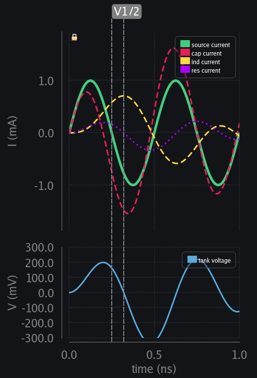
When 1GHz Tank is Excited with 0.5GHz Frequency
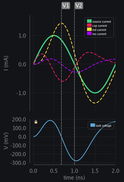
Things play out as usual. Cap and resistor start by taking all the current from source. Ind picks up the pace, and slowly starts taking current. A point comes where not enough current is available from source to keep providing for all three (ind, cap, res). Someone has to give up. Ind cannot because it does not like sudden change in current. Cap gives up and its current starts reducing. All of this looks normal transient behavior as we saw in case of resonant frequency. The difference comes from zero crossings. See now cap voltage and source currents zero crossings are not aligned which they were in resonant case. So at V1 (in left image below) cap is in a position to discharge but source still wants to go positive. Its zero crossing comes later at V2. Now instead of reverse charging the cap and ind also helping the process (as happened at V6 for resonant frequency cases described above), source tries to charge cap positively again whereas ind is still trying to reverse charge. Overall, result is that total charge or voltage build-up across cap is lesser. This goes on in every cycle, and cap is never able to develop a higher voltage. Now question is how much lesser voltage is produced compared to resonant case? Ans: the farther the zero crossing of cap voltage from source current, the lesser the voltage developed. It does not matter if source zero crossing comes earlier or later, what matters is how far away is it.
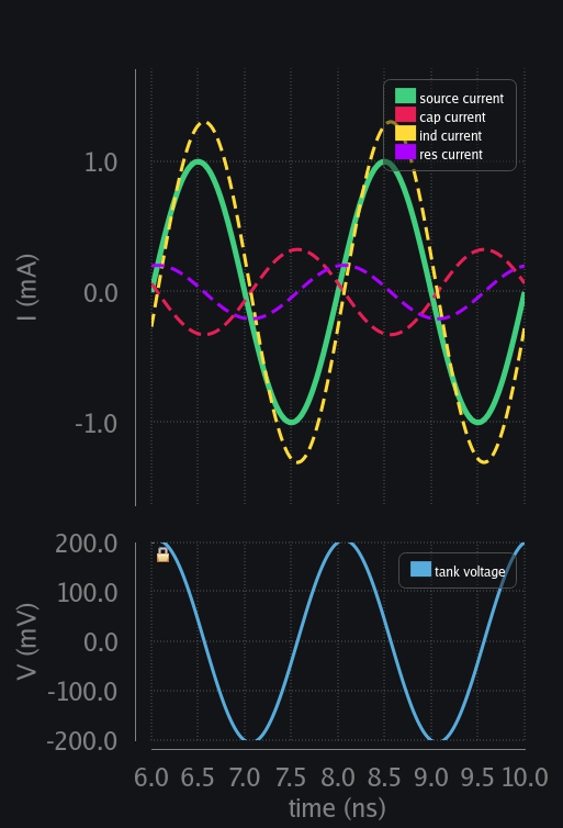
Note left and right image below are response of same LC tank. Just that left shows initial transient behavior, and right shows when things have settled.
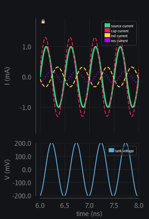
When 1GHz Tank is Excited with 2GHz Frequency
Nothing much to say here. It emphasizes the same thing that when zero crossings are not aligned, things will not go in your favor. For example, you can observe that resistor current and source current are not in phase, so the resistor would never be able to draw all of source current and develop the max voltage it could. And they are not in phase because the way cap voltage developed and when source zero crossing came in didn’t align (V1 and V2 in left image below).
Frequency Response of LC tank in general
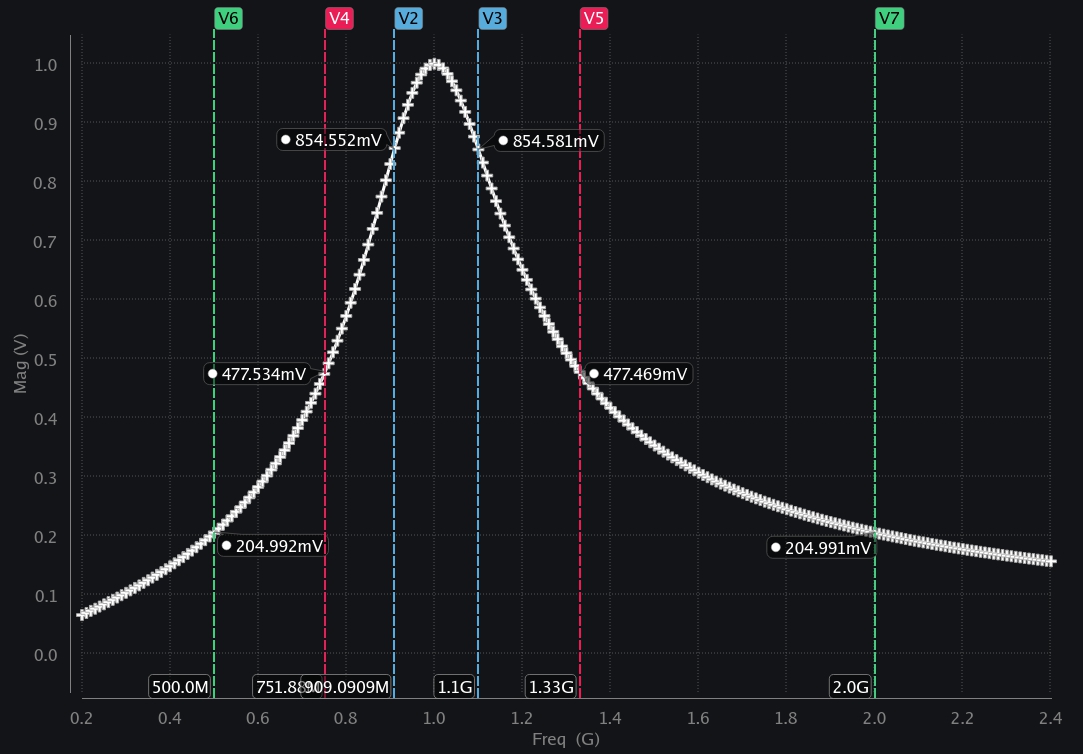
The LC tank of 1GHz resonance frequency and quality factor of ~3 is excited with different frequencies and the voltage developed across tank is plotted in image below.
Interesting thing to note here that is that if you excite at x times higher or x times lower frequency than resonance frequency, the voltage developed is same. For example, at \(1.1f_o\) or \(\dfrac{f_o}{1.1}\), the voltage developed is about 854mV. Similarly, at \(1.33f_o\) or \(\dfrac{f_o}{1.33}\) voltage developed is again same (~477mV). This tells us that a resonator behaves in a geometric fashion that is if you were to look at voltage developed at \(f_o+x\) and \(f_o-x\) it will not be same; but if you were to look at \(xf_o\) and \(\dfrac{f_o}{x}\), it will be exactly the same. How can we explain this – let’s explore that in next chapter.