4FMODs and Counter IM3
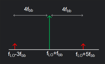
New to transmitter design? Trying to understand what metrics are used by industry for transmitter design? You might have heard of primary 4FMOD (also called CIM3) and secondary 4FMOD (also called CIM5). Unlike traditional IM3 which is generated by intermodulation of two tones, CIM3 and CIM5 are primarily generated by distortion products of a single tone. They are important because they lie very close to signal, only \(4f_{bb}\) away.
If you are transmitting a signal at \(f_{LO}+f_{bb}\), then on lower side of LO at \(f_{LO}-3f_{bb}\) lies your primary 4FMOD (or CIM3) and on higher side of LO at \(f_{LO}+5f_{bb}\) lies secondary 4FMOD (or CIM5).

Immediately you must ask: what about \(f_{LO}+3f_{bb}\), that lies even closer, \(2f_{bb}\) away from signal but you don’t talk about it? Correct but in an IQ transmitter it gets cancelled out, and since all the TX are IQ nowadays (for single side band modulation), it doesn’t matter much. What cancels and what survives in an IQ mixer? See the math below.
IQ Mixer – The Math
Consider an IQ transmitter. I channel DAC generates cosine signal, and Q channel DAC generates 0.25\(T_{bb}\) shifted signal of I channel (or in other words 90 degree shifted for fundamental):
where \(A_{1}\) is a linear gain coefficient, \(A_{3}\) is 3rd order distortion coefficient and \(A_{5}\) is 5th order distortion coefficient. Check out single tone distortion.
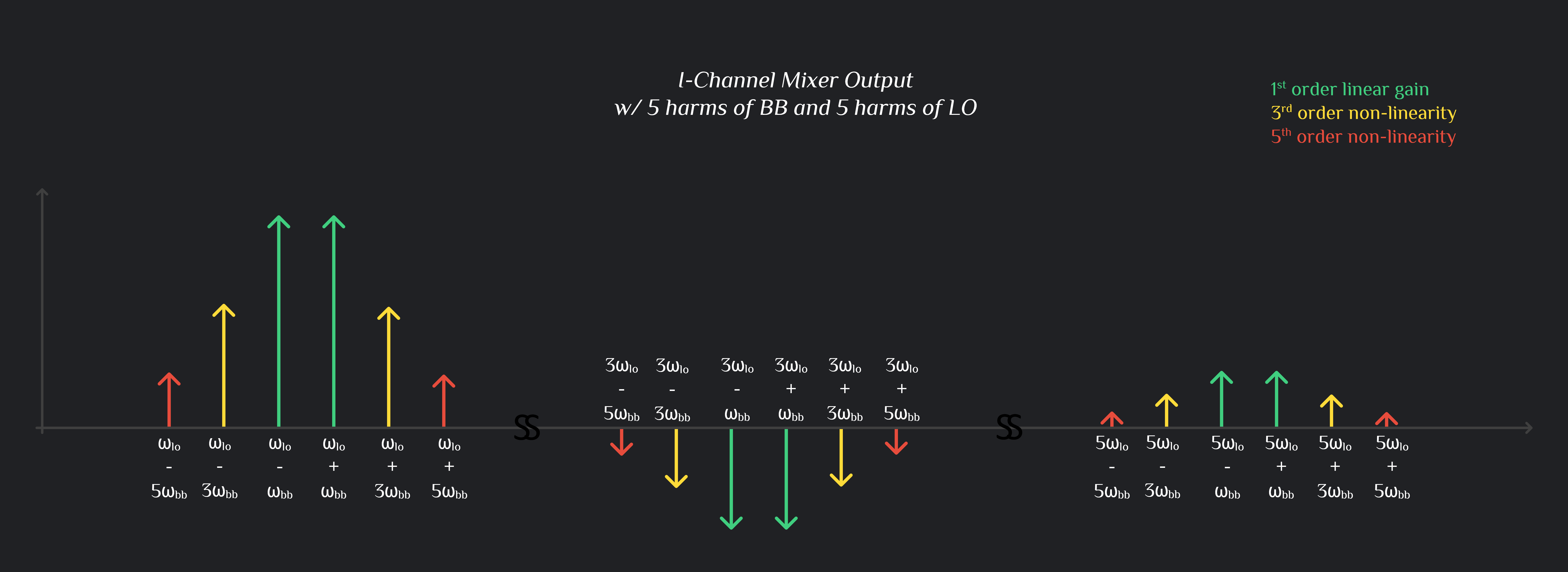
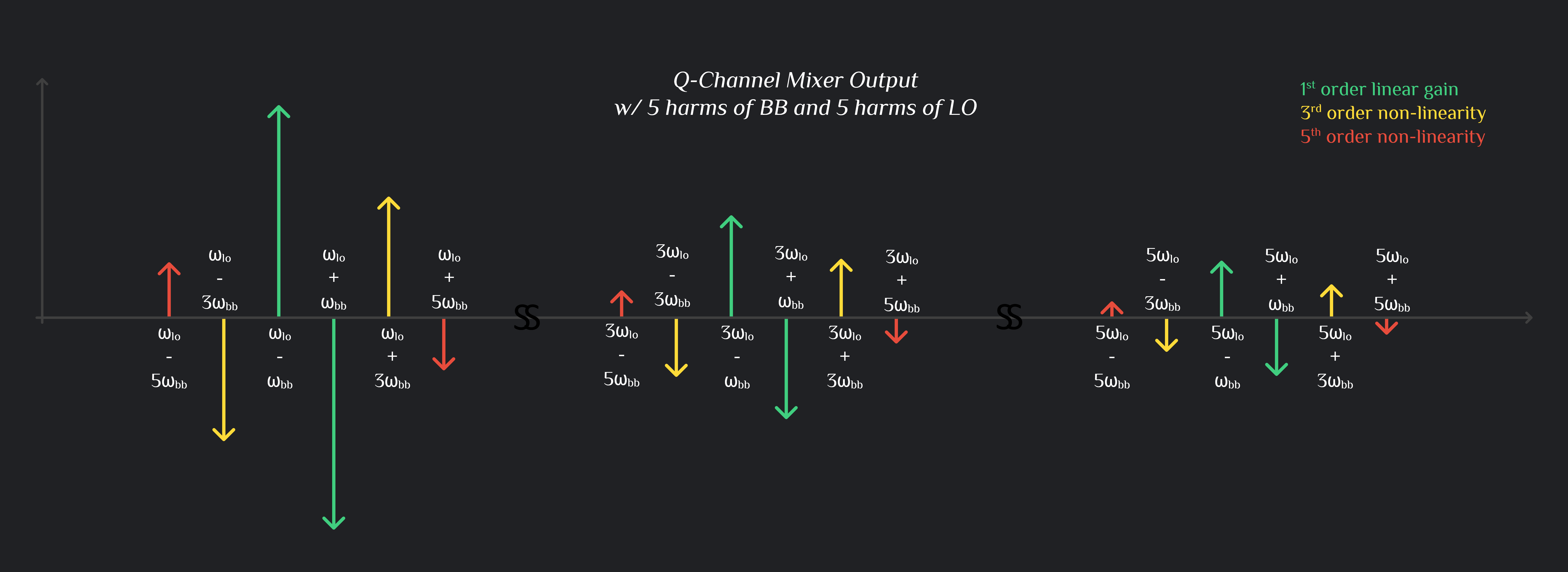
I channel baseband signal is multiplied by I channel LO, and Q with Q. We can write mixer output as:
I Channel Mixer Output

Q Channel Mixer Output

I & Q Mixer Output Combined
Now this is where it gets interesting. When I and Q channel outputs are added, a lot of products cancel out. These tones are left out:
It’s also interesting to note that Primary 4FMOD always falls on the opposite side of signal and secondary 4FMOD falls on the same side. Also note that \(3\omega_{LO}\) and \(5\omega_{LO}\) related products eventually get filtered by your matching network (but before matching network, they still exist, on all the nodes of your circuits, beware), and only \(\omega_{LO}\) products make it to your antenna.

Story is not finished yet…
There is another dominant way Primary 4FMOD is generated when signal (\(\omega_{lo}-\omega_{bb}\)) and 3LO upconverted signal (\(3\omega_{lo}+\omega_{bb}\)) pass through cubic non-linearity of next stage (say PA driver amplifier). They intermodulate and their IM3 lands at Primary 4FMOD [2].This is also demonstrated in the image below (note: here we are showing upper sideband of signal \(\omega_{lo}+\omega_{bb}\), so primary 4fmod falls at \(\omega_{lo}-3\omega_{bb}\))

References:
RFInsights
Date Published: 15 Oct 2022
Last Edit: 01 Feb 2023